Difference between revisions of "Output Channel Selector Kit"
IVSWikiBlue (talk | contribs) (→Wiring Diagram) |
IVSWikiBlue (talk | contribs) |
||
| (4 intermediate revisions by the same user not shown) | |||
| Line 1: | Line 1: | ||
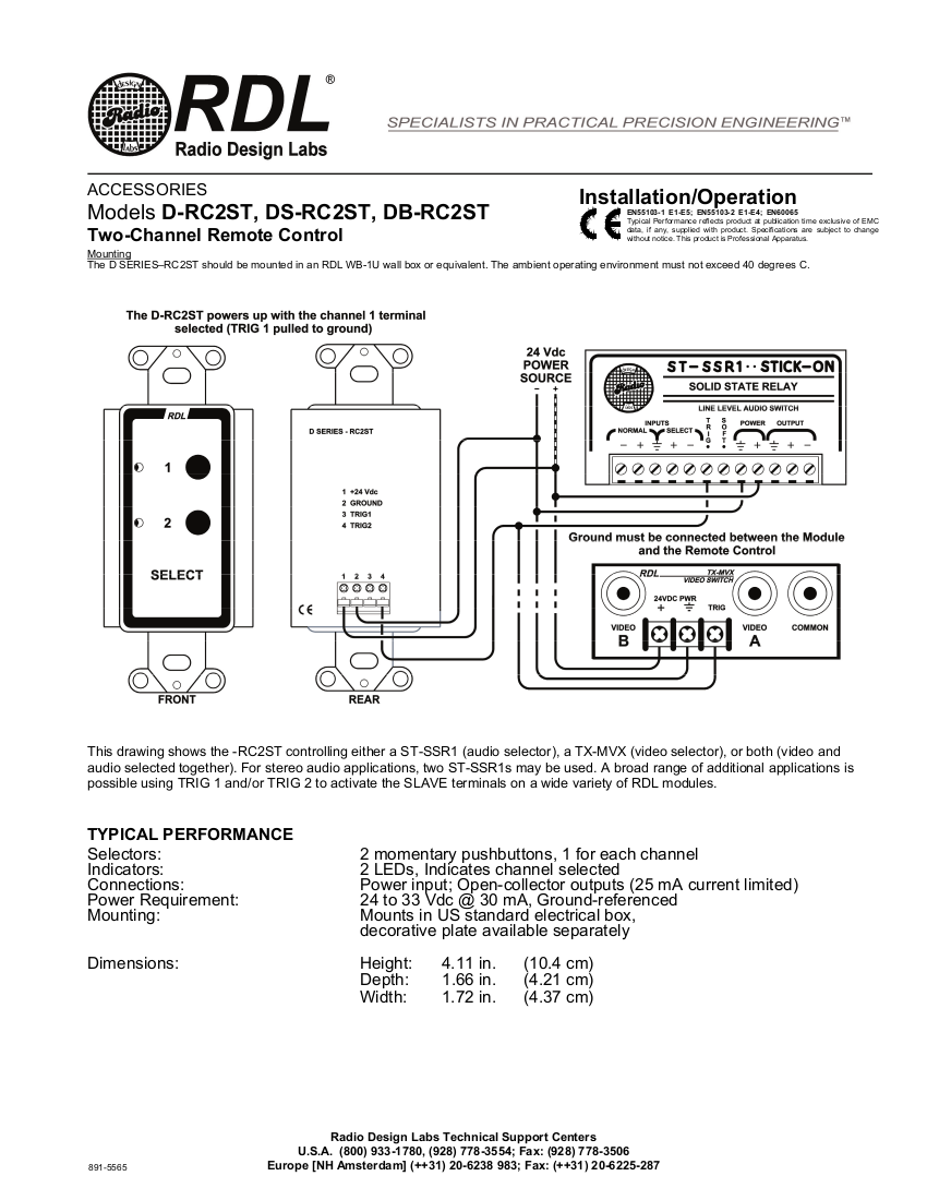
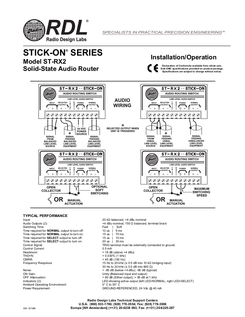
| − | == | + | ==Device Data Sheets== |
| − | + | {{img | file = Db-rc2st page2.png}} {{img | file = St-rx2 page2.png}} | |
==Required Parts and Tools== | ==Required Parts and Tools== | ||
| Line 21: | Line 21: | ||
#Using a pencil, mark out where the switching button will be located | #Using a pencil, mark out where the switching button will be located | ||
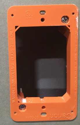
#Cut a hole into the drywall, large enough to fit the mud ring into it securely. | #Cut a hole into the drywall, large enough to fit the mud ring into it securely. | ||
| − | #: | + | #: {{img | file = VerifactDring.JPG | width=170px}} |
#Cut a hole above the drop ceiling to fish lines (if necessary) | #Cut a hole above the drop ceiling to fish lines (if necessary) | ||
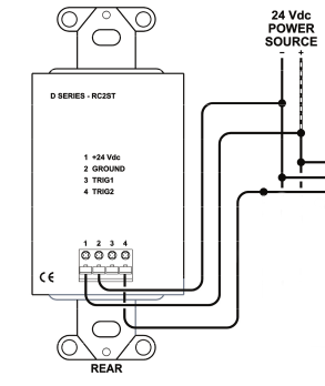
#Using fish tape or glow rods, pass three lines of 22/2 behind the drywall, two for signal control and one for power. (shown below) | #Using fish tape or glow rods, pass three lines of 22/2 behind the drywall, two for signal control and one for power. (shown below) | ||
| − | + | #:{{img | file = Db-rc2st wiring.png}} | |
#Once the lines are ran, mount the selector to the mud ring | #Once the lines are ran, mount the selector to the mud ring | ||
#Gently secure the face plate once mounted | #Gently secure the face plate once mounted | ||
| Line 31: | Line 31: | ||
#Determine above the ceiling where the ST-RX2 will be mounted | #Determine above the ceiling where the ST-RX2 will be mounted | ||
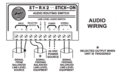
#Connect the lines ran from the DB-RC2ST as shown | #Connect the lines ran from the DB-RC2ST as shown | ||
| − | + | #:{{img | file = St-RX2 wiring2.png}} | |
''Note:'' The ST-RX2 and DB-RC2ST will draw from the same power source and can be connected together using a terminal block | ''Note:'' The ST-RX2 and DB-RC2ST will draw from the same power source and can be connected together using a terminal block | ||
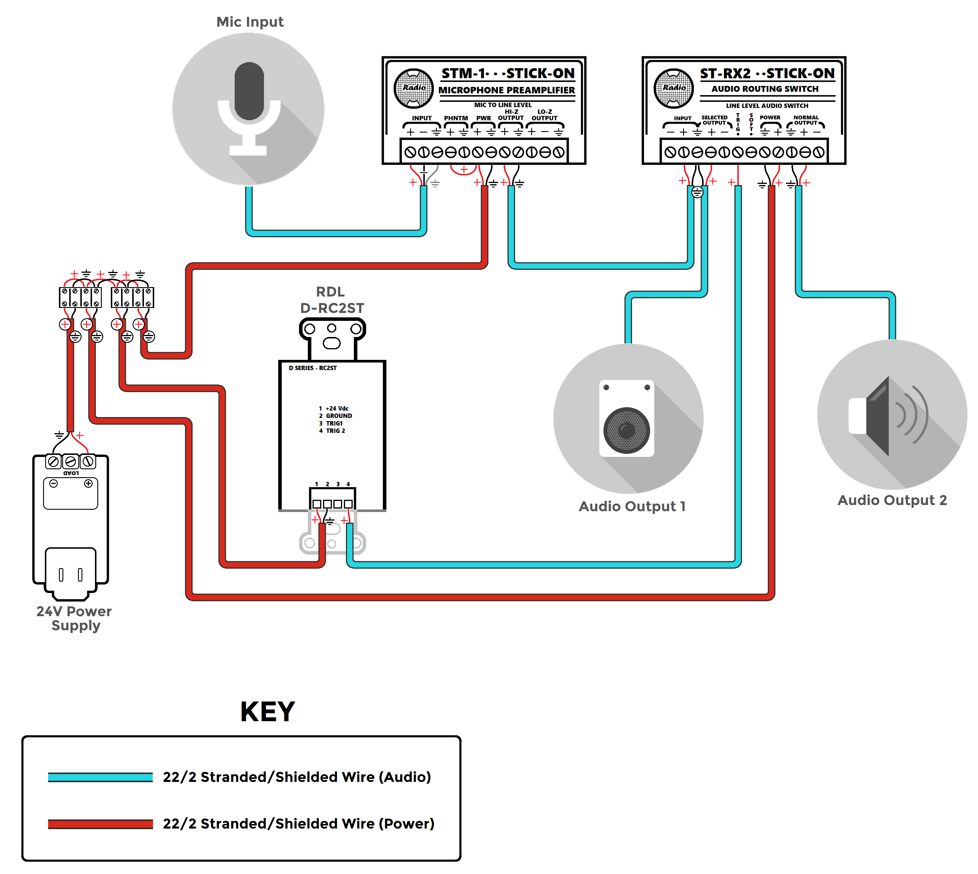
| − | == | + | ==Wiring Diagram== |
| − | + | {{img | file = ST-RX2 General Diagram.png | width=1000px}} | |
Latest revision as of 14:05, 11 May 2022
Contents
Device Data Sheets
Required Parts and Tools
- RDL ST-RX2
- RDL D-RT2ST
- RDL 24 V power supply
- Stud finder
- Fish tape or Glow Rods
- Drywall Saw
- Small Screwdriver
- Face plate screws
- Shielded Stranded 22/2 + ground Wire
- (1) terminal block
- (1) Single Gang mud ring
- (1) Single gang decorative faceplate
"Note:" If used with Control Room Audio kit, triple gang mud rings will be used
Mounting the Button
- Using a stud finder, scan the mounting location of the DB-RC2ST to ensure the device is not mounted on a stud.
- Using a pencil, mark out where the switching button will be located
- Cut a hole into the drywall, large enough to fit the mud ring into it securely.
-
- Cut a hole above the drop ceiling to fish lines (if necessary)
- Using fish tape or glow rods, pass three lines of 22/2 behind the drywall, two for signal control and one for power. (shown below)
- Once the lines are ran, mount the selector to the mud ring
- Gently secure the face plate once mounted
Wiring the ST-RX2
- Determine above the ceiling where the ST-RX2 will be mounted
- Connect the lines ran from the DB-RC2ST as shown
Note: The ST-RX2 and DB-RC2ST will draw from the same power source and can be connected together using a terminal block
Wiring Diagram